What Are You Looking For?
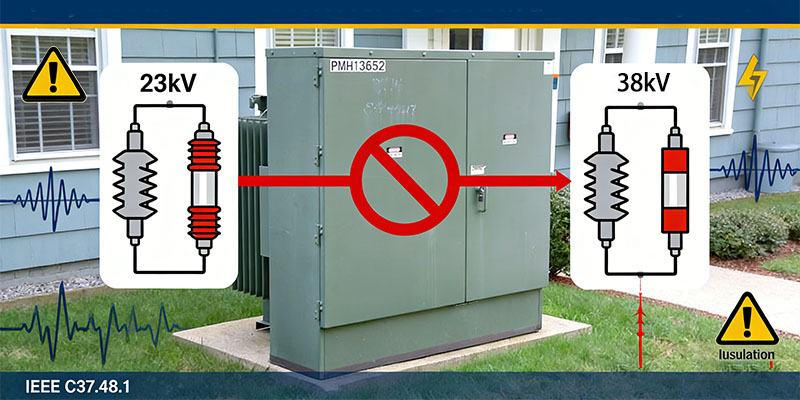
In electrical procurement and field maintenance, a seemingly logical instinct often surfaces: bigger must be safer. If a 23 kV fuse works, then selecting a 38 kV fuse—with higher insulation class and stronger arc-quenching capability—should provide an extra margin of protection.
It sounds reasonable. It is also dangerously wrong.
In high-voltage current-limiting fuse applications, this well-intentioned substitution can silently devastate transformer insulation. Guided by IEEE C37.48.1, the following analysis dismantles the physics, standards, and engineering realities behind this critical rule.
Current-limiting fuses earn their reputation by acting fast. Extremely fast. But speed has a price.
When a severe fault current flows, the silver fusible elements inside a current-limiting fuse vaporize almost instantaneously. The surrounding quartz sand melts and vitrifies, forming a highly resistive plasma channel.
This process generates a reverse electromotive force—a very high arc voltage—that forces the fault current to collapse before reaching its natural peak.
The higher the rated voltage of the fuse, the longer and more complex its internal arc path.
Longer arc path means higher arc voltage.
Higher arc voltage means a more violent electrical event imposed on the system.
This is not a theoretical nuance. It is the central risk.
IEEE C37.48.1, Clause 6.1.3.5, draws a sharp line engineers are not allowed to blur:
Peak arc voltage must be coordinated with the insulation level of the protected equipment.
A standard 19.92 kV transformer typically has a Basic Impulse Level (BIL) of:
125 kV (common)
150 kV (upgraded designs)
This BIL defines how much transient voltage stress the transformer insulation can tolerate—once, briefly, and with limited repetition.
A 38 kV current-limiting fuse, interrupting a high-magnitude fault, can generate peak arc voltages in the range of 100–120 kV or higher.
That voltage does not exist in isolation.
It stacks on top of:
System voltage
Switching transients
Reflected wave phenomena inside the transformer windings
The transformer may not fail immediately.
Instead, its turn-to-turn insulation experiences microscopic damage.
Partial discharges begin.
Aging accelerates.
Eventually, an internal dielectric breakdown occurs—often months or years later—seemingly without cause.
The root cause, however, was installed long before.
Clause 6.1.8 of IEEE C37.48.1 addresses a detail often ignored in the field: system grounding.
In a 34.5 kV GrdY / 19.92 kV system, the transformer primary is connected phase-to-ground.
That means:
The maximum recovery voltage across the fuse after interruption is 19.92 kV, not 34.5 kV.
The fuse never needs to withstand line-to-line voltage.
IEEE guidance recommends fuse ratings between 100% and 140% of the maximum phase-to-ground voltage.
For 19.92 kV systems, this places optimal fuse ratings at:
23 kV
27 kV
This range provides adequate dielectric margin without inducing destructive arc overvoltage.
Using a 38 kV fuse introduces nearly 200% voltage headroom where none is needed.
This is not redundancy.
It is miscoordination.
The fuse becomes electrically incompatible with the transformer it is meant to protect.
External insulation components—such as bushings—can safely be overrated.
A 35 kV bushing on a 19.92 kV system poses no risk because it does not participate in fault interruption or arc generation.
Internal protective devices are different.
Current-limiting fuses must be matched, not oversized.
For 19.92 kV transformers, the correct choice is 23 kV or 27 kV ELSP-type fuses, coordinated for both short-circuit current and insulation stress.
Electrical safety is not achieved by piling on insulation or choosing the largest rating available.
It is achieved through dynamic energy balance—between fault current, arc voltage, and dielectric endurance.
In 19.92 kV pad-mounted transformer protection, abandon the myth that “bigger is safer.”
Precision is protection.
And in this case, 23 kV is the only responsible choice.