What Are You Looking For?
In the design of distribution transformers—especially pad-mounted American-style units—the four-position sectionalizing loadbreak switch is a decisive component. It determines not only how power flows, but how safely it flows. Manufacturers offer multiple blade configurations to accommodate different grid topologies. Selecting the wrong blade type does more than compromise functionality; it can precipitate catastrophic loop-closing incidents, upstream protection trips, or transformer failure.
Drawing on current technical manuals and field practice, the following guide dissects blade classifications, switching logic, and real-world applications.
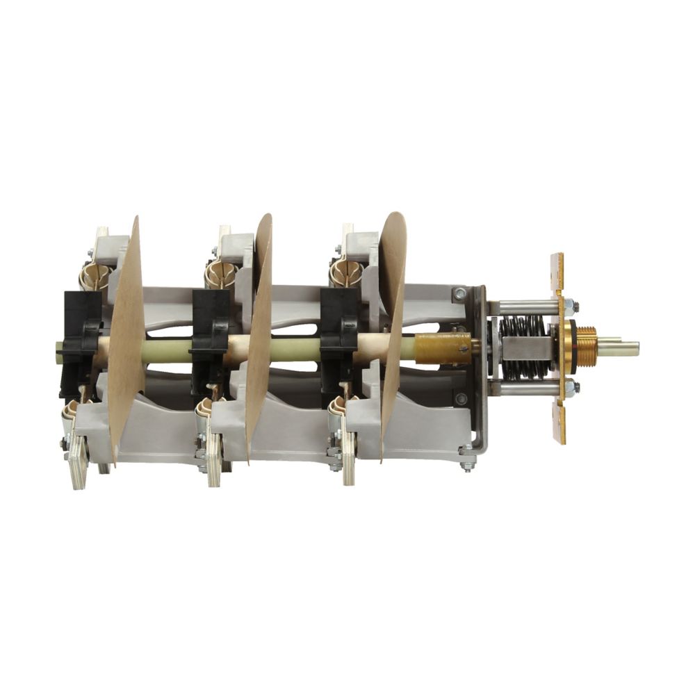
A four-position switch typically operates through a rotary handle, indexed into four discrete detents. At first glance, these positions appear uniform across products. In reality, their electrical meaning is entirely dictated by two factors:
Blade geometry (Blade Type)
Internal connection schematic (Switching Logic)
In other words, identical handle positions can represent radically different circuit states depending on the blade design. Understanding this distinction is the foundation of correct selection.
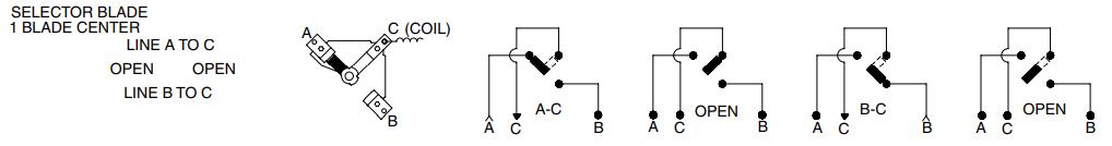
The defining characteristic of selector-type switches is simplicity. Only one moving contact blade exists. This physical constraint drives their safety behavior.
Typical application: Dual-source manual transfer.
Function:
The switch selects between two independent power sources—Line A or Line B—to feed the transformer.
Safety logic:
Because there is only a single blade, any transition from Line A to Line B must pass through a true OPEN position. This enforces a hardwired Break Before Make sequence. The two sources can never be electrically bridged, even momentarily.
This mechanical inevitability provides absolute protection against unintended paralleling or loop closure. No interlocks. No control logic. Just physics.
Typical application: Single-source isolation.
Function:
Provides a straightforward ON/OFF control for one incoming feeder. No source selection. No loop functionality.
This blade is often chosen where isolation, not redundancy, is the primary requirement.
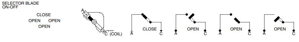
The V-Blade introduces complexity—and flexibility. Its two branching contacts form a “V” geometry.
Typical application: Urban loop distribution networks.
Function:
The transformer can be connected to Line A, Line B, or both simultaneously (A + B).
Switching logic:
V-Blades may be configured for Make Before Break, allowing a brief overlap where both sources are connected. This enables source transfer without interrupting supply, a critical feature in densely populated or mission-sensitive networks.
The trade-off is risk. Make Before Break operation assumes both sources are synchronized in phase and voltage. Without that condition, the overlap becomes a liability rather than a benefit.
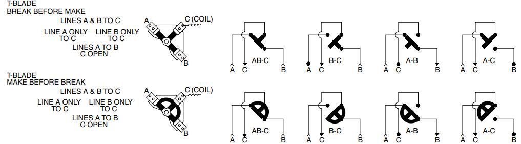
The T-Blade is the most versatile—and the most misunderstood. It incorporates three branching contacts, enabling unique feed-through behavior.
Typical application: Online maintenance at critical nodes.
Defining feature:
A dedicated position labeled “Lines A to B, C OPEN.”
Practical meaning:
The main feeder remains energized from A to B, supplying downstream loads, while the local transformer (C) is completely isolated.
This configuration is indispensable when the network must remain live but the transformer requires inspection, oil sampling, or repair. No alternative blade type can replicate this function safely.
User requirement:
“A three-phase transformer must switch between two sources. Under no circumstances may it be connected to both simultaneously.”
Recommended selection sequence:
Switch type: LS4 (Four-Position Loadbreak Switch)
Phase configuration: 3 (Three-Phase)
Blade type: Selector Blade — D or R
Switching logic: Break Before Make (B)
Rationale:
Both V-Blade and T-Blade designs inherently include positions where A and B can be connected at the same time. That violates the stated safety boundary. Selector blades physically preclude this condition.
Counting positions is insufficient. The internal schematic matters more than the handle label.
Maximum isolation, zero misoperation risk: Selector Blade (D/R)
Flexible loop operation with no outage: V-Blade
Live feeder continuity with local isolation: T-Blade
Blade selection is not an accessory decision. It is system architecture.
Pain point:
Dual utility feeds often originate from different substations. Phase misalignment is common. Any loop closure can induce massive circulating currents, damaging transformers and collapsing UPS systems.
Recommended blade: Selector Blade (D or R)
Operational logic:
During maintenance, operators transfer the load from Source A to Source B. The mandatory OPEN position enforces Break Before Make, ensuring the two sources never meet. Servers stay protected. Downtime is avoided.
Pain point:
Continuous-process industries cannot tolerate full line outages. Yet transformers still require service.
Recommended blade: T-Blade (Code T)
Typical feed-through scenario:
The switch is set to Lines A to B, C OPEN. Power flows uninterrupted through the ring. The local transformer is electrically isolated. Maintenance proceeds safely. Production continues.
Pain point:
Planned switching operations must be invisible to end users.
Recommended blade: V-Blade with Make Before Break configuration.
Operational logic:
The switch briefly enters an A + B state before disconnecting the old source. Loads experience no interruption. This is only permissible when both sources are fully synchronized—same phase, same frequency, same voltage.
| Industry Sector | Core Requirement | Recommended Blade | Key Configuration |
|---|---|---|---|
| Data Centers | Prevent non-synchronous loop closure | Selector (S/D) | D/R + B |
| Industrial Plants | Maintain feeder, isolate transformer | T-Blade | T + B or M |
| Urban Distribution | No-outage source transfer | V-Blade | V + M |
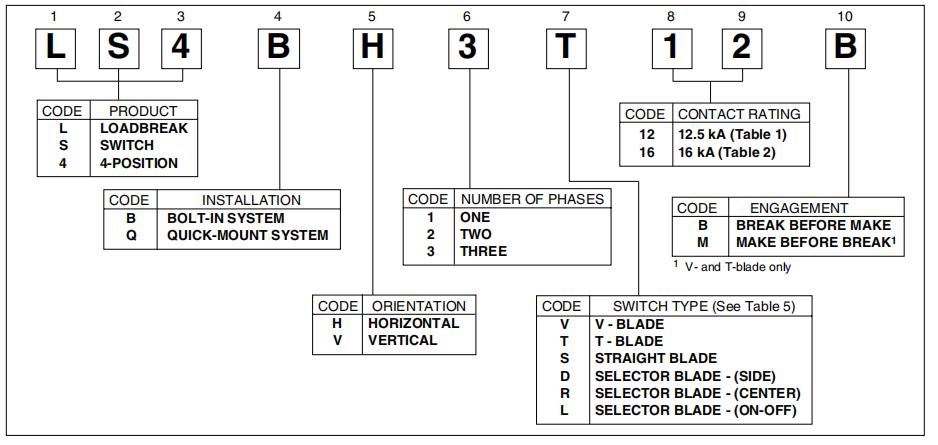
Expert Note:
For three-phase systems, the model designation must include code 3. Always verify interrupting ratings—such as 12.5 kA or 16 kA—against the site’s prospective short-circuit current. Blade logic governs safety; interrupting capacity governs survival.