What Are You Looking For?
In power system protection, the word fuse is often dismissed by non-specialists as shorthand for a simple, sacrificial wire. An expendable component. An expensive inconvenience.
That casual perception collapses instantly when the voltage climbs into the realm of 19.92 kV or 34.5 kV distribution systems. At these levels, selecting the wrong type of fuse is not a minor specification error—it can be the difference between controlled fault isolation and catastrophic equipment destruction.
Guided by IEEE C37.48.1, this article dissects two fundamentally different protection technologies: the expulsion fuse and the current-limiting fuse. They may share a name. They do not share a mission.
Expulsion fuses—most familiarly encountered as drop-out cutouts—represent one of the oldest and most widely deployed protective devices in medium-voltage networks. Their effectiveness lies in simplicity and physics rather than speed.
When an overcurrent causes the fusible element to melt, an electrical arc forms inside the fuse tube. This arc rapidly heats the tube’s internal gas-generating liner. In response, high-velocity gas is expelled outward, forcibly elongating and cooling the arc column.
The interruption mechanism depends on a crucial phenomenon:
the natural current zero crossing of the AC waveform.
As the current passes through zero, the arc—already stretched and weakened by gas expulsion—fails to re-ignite, and the circuit is interrupted.
This approach has a critical constraint. The fuse cannot interrupt immediately. It must endure the full rise of the fault current until the next current zero occurs.
In severe short-circuit events, that means the protected system experiences the entire prospective peak fault current. Mechanical forces surge. Thermal stress accumulates. Equipment absorbs everything the network can deliver—until the fuse finally clears.
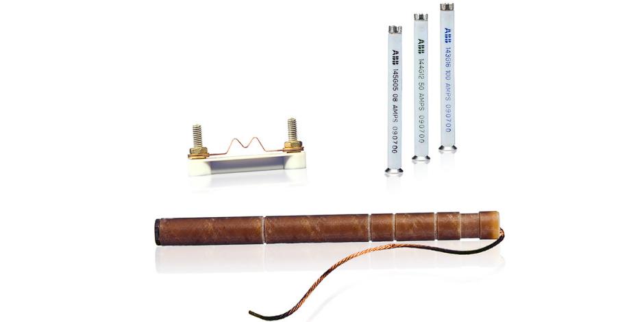
Current-limiting fuses operate on a radically different philosophy. According to IEEE C37.48.1, Clause 4, their defining characteristic is not extinction—it is suppression.
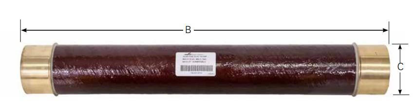
A current-limiting fuse typically consists of finely calibrated silver fusible elements embedded in quartz sand. When a high-energy fault occurs, the fusible element vaporizes almost instantaneously. The surrounding quartz sand melts and vitrifies, forming a dense, high-resistance medium.
This transformation generates an exceptionally high arc voltage across the fuse.
That arc voltage actively forces the fault current downward, preventing it from ever reaching its theoretical peak. The interruption is not passive. It is coercive.
In practical terms, the entire fault event is often terminated in less than half an electrical cycle—approximately 8.3 milliseconds. The system never experiences the mechanical or thermal extremes it otherwise would.
Speed, here, is not convenience. It is survival.
Despite serving the same broad purpose, expulsion and current-limiting fuses are not functionally equivalent. Clause 4.6 of the standard makes this distinction unambiguous.
The integral of current squared over time—I²t—represents the total thermal energy delivered into a faulted system.
Expulsion fuses allow high I²t values to pass downstream.
Current-limiting fuses drastically constrain I²t, often by an order of magnitude.
For sealed equipment such as pad-mounted transformers, limiting I²t is not optional. It is the only effective method to prevent internal oil vaporization, tank rupture, or explosive failure during high-energy faults.
One nuance is frequently overlooked. When current-limiting fuses operate, the arc voltage they generate can be substantial. If the fuse voltage rating is mismatched to the system—such as applying a 38 kV fuse on a 19.92 kV system—the resulting overvoltage can exceed the transformer’s insulation withstand capability.
IEEE C37.48.1 Clause 6.1.3.5 explicitly warns that improper selection can result in dielectric breakdown initiated by the protective device itself.
Protection, misapplied, becomes the hazard.
The answer is not binary. Each fuse type serves a distinct role in a layered defense strategy.
Best suited for:
Low-level overloads
Secondary-side faults
Easily accessible, serviceable protection points
They are economical, visible, and simple to replace. In system architecture, they function as front-line sentries.
Designed for:
High-energy primary faults
Internal transformer failures
Scenarios where mechanical and thermal stress must be minimized
They act as the final barrier, sacrificing themselves to prevent irreversible damage to sealed equipment.
Modern high-voltage pad-mounted transformer designs rarely rely on one alone. The most robust approach is a series coordination scheme:
Expulsion fuses manage minor, frequent disturbances.
Current-limiting fuses stand ready to arrest catastrophic events.
Together, they form a hierarchy of protection—measured, deliberate, and unforgiving to faults, but merciful to equipmen