What Are You Looking For?
![]()
Transformer tap changers operate on a straightforward yet powerful principle: altering the tap position changes the number of winding turns in operation, which in turn modifies the transformation ratio. This ratio, expressed as:
where and are the primary and secondary winding turns respectively, and U1 and U2 are the primary and secondary voltages, dictates the relationship between input and output voltages.
When the tap changer is on the primary side, adjusting its position directly changes the primary winding turns, thereby affecting K. A shift in K means that, for the same applied voltage U1, the secondary voltage U2=U1/K will vary accordingly. This mechanism enables precise control over the output voltage.
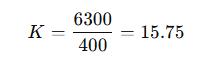
For instance, consider a 6000 ± 5% / 400 V step-down transformer. At the rated tap, the transformation ratio is:
![]()
If the high-voltage side is energized at 6000 V, the secondary outputs 400 V. To lower the secondary voltage, K must be increased—achieved by increasing the number of primary turns. Shifting the tap to the +5% position results in:
Under the same 6000 V input, the secondary voltage becomes:
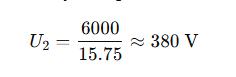
Thus, voltage regulation is effectively the outcome of manipulating the turns ratio.
In principle, taps could be placed on either the primary or secondary winding. However, for off-load tap changers (also known as no-load or de-energized tap changers), the taps are almost always located on the high-voltage side. There are two practical reasons for this:
Ease of Construction – In most transformer designs, the high-voltage winding is wound over the low-voltage winding. This positioning makes it mechanically simpler to bring out tap leads and connect them to the selector switch.
Reduced Current Handling – The high-voltage side carries lower current compared to the low-voltage side. This allows the tap changer contacts to be smaller in cross-section, reduces thermal stress, and makes mitigation of contact resistance issues easier.
In a three-phase transformer, each phase of the primary winding typically has three terminals: the central tap corresponds to 100% of the turns, and the other two to ±5% variations. Across three phases, this results in nine leads connected to the tap changer.
When the selector connects all 100% taps together, the transformer operates at its nominal primary voltage (e.g., 10 kV). Switching to the +5% taps increases the number of primary turns, thus requiring 10.5 kV on the primary to produce the same secondary voltage. Conversely, selecting −5% taps decreases the number of primary turns, requiring only 9.5 kV for nominal secondary output.
Because these adjustments physically alter the winding configuration, the transformer must be completely de-energized before operating an off-load tap changer—hence the term no-load tap changer.
Electrical grids are dynamic systems. Voltage levels fluctuate due to changes in load, power flow patterns, and system operating conditions. Excessive deviation—either high or low—can shorten equipment lifespan, reduce efficiency, and cause operational instability.
To maintain supply quality, tap positions are adjusted according to the “high to high, low to low” rule:
Consider a high-voltage winding with three tap positions:
Position 1: 10,500 V → 400 V output
Position 2: 10,000 V → 400 V output
Position 3: 9,500 V → 400 V output
If the actual high-voltage supply is constant at 10,000 V:
Selecting Position 1 yields a lower secondary voltage than nominal (because more primary turns reduce the output).
Selecting Position 3 yields a higher secondary voltage (because fewer primary turns boost the output).
This is the essence of “high to high, low to low”—a counterintuitive yet reliable rule born from the mathematics of transformer ratios.