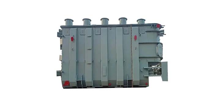
(3) Tank Assembly
The welded steel tank serves multiple functions:
- Structural containment for core/winding assembly
- Dielectric insulation medium (transformer oil)
- Heat transfer system (natural convection)
- Capacity expansion options: Radiators/heat exchangers for large-capacity units
Transformer oil specifications:
- Mineral oil with dielectric strength ≥30 kV
- Three grades: No.10 (-10°C), No.25 (-25°C), No.45 (-45°C) based on environmental requirements
(4) Conservator System
The expandable oil reservoir (10% tank volume) features:
- Capsule-type air separation design
- Automatic volume compensation (±8% capacity variation)
- Integrated oil level indicator with temperature-compensated scales:
• +40°C (maximum full load level)
• +20°C (normal operating reference)
• -30°C (minimum no-load level)
- Breathing apparatus with silica gel moisture absorption
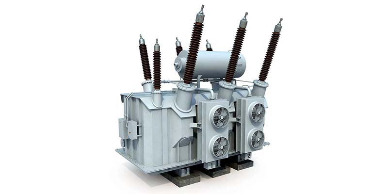
(5) Bushing System
Insulating assemblies connect internal windings to external circuits:
(6) Explosion-proof Device
Safety valve system:
- Rupture disc design (set pressure 50kPa±10%)
- Automatic pressure relief during internal faults
- Integrated fault signaling mechanism
(7) Gas Relay Protection
Differential protection system:
- Dual-stage protection (signal + trip)
- Gas analysis capability (air vs. combustible gases)
- Oil flow monitoring with directional sensing
(8) Temperature Monitoring
Critical parameters:
- Top oil temperature limit: 95°C (continuous), 85°C (recommended)
- Winding temperature limit: 105°C (emergency)
- Alarm activation at 80°C (oil)/100°C (winding)
(9) Neutral Point Grounding
System protection requirements:
- Compulsory grounding for 110kV graded insulation systems
- Preventive measure against ferroresonance overvoltages
- Maintenance grounding protocol during shutdowns
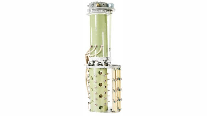
(10) On-load Tap Changer
Voltage regulation system:
- Separate conservator with non-capsule design
- Operation sequence: Stepwise adjustment with 1-minute intervals
- Emergency stop procedure for multiple position shifts
- Maintenance cycle: Every 5000 operations or 3 years
2.Operational Practices
(1) Normal Operating Modes
A. Rated Conditions
- Ambient temperature: -25°C to +40°C
- Oil temperature rise: ≤55K (top oil)
- Load current: 100% rated value
B. Permissible Overloads
- Continuous: 1.1 times rated current (≤8h)
- Short-term: 1.3 times rated current (≤2h)
- Seasonal: 1.2 times rated current (ambient ≤+15°C)
(2) Abnormal Conditions & Responses
A. Immediate Shutdown Criteria
- Internal explosions or violent discharges
- Temperature runaway (>10°C above normal)
- Oil ejection from explosion-proof device
- Oil level below minimum mark
- Carbonaceous deposits in oil
- Severe bushing flashover
B. Overload Management Protocol
- Verify load vs. cooling capacity correlation
- Check cooling system integrity
- Monitor winding temperatures (thermocouples)
- Initiate forced cooling if ΔT >10°C
C. Gas Relay Activation Procedure
- Perform dissolved gas analysis (DGA)
- Check oil sampling for combustibility
- Inspect core and winding insulation
- Implement oil processing if necessary
(3) Maintenance Requirements
A. Routine Inspection Items
- Acoustic monitoring for partial discharges
- Oil level verification (±5% tolerance)
- Thermographic analysis of connections
- Breather system functionality check
- Cooling fan vibration analysis
B. Periodic Maintenance Schedule
- Quarterly: Bushing leakage test, oil dielectric strength test
- Annually: Core and clamp insulation resistance, winding deformation test
- Biennially: Furan content analysis, oil chromatography
C. Specialized Testing
- Impulse withstand test (1.5/5μs waveform)
- Partial discharge mapping (>100pC threshold)
- Short-circuit withstand verification
This technical specification provides comprehensive guidelines for the operation, maintenance, and troubleshooting of three-phase oil-immersed transformers, emphasizing safety compliance and equipment longevity through systematic condition monitoring.