What Are You Looking For?
The 10kV distribution ring main unit is a vital component in medium-voltage power distribution systems. Its primary function is to ensure the safe and stable delivery of 10kV or even 35kV high-voltage electricity to end users. Beyond distribution, it also enables monitoring and control of transformers within the network, ensuring continuous and secure operation. Despite its pivotal role, the RMU is compact and lightweight, offering high performance with operational ease. The following sections delve into the comprehensive aspects of this essential equipment.
A ring main unit is a type of compact switchgear housed in a metal enclosure, often made of stainless steel or galvanized steel. It primarily incorporates load break switches and high-voltage fuses, forming the core of its switching function. RMUs are favored for their straightforward design, minimal footprint, cost-effectiveness, and enhanced supply reliability and safety.
While technically there is no formal switchgear category named “ring main unit” in equipment standards, it has become an industry-accepted term. Initially referring to load switch cabinets used in ring distribution networks, the term has since evolved to describe any cabinet employing load break switches, regardless of its network topology.
These units facilitate key operations such as ring closure (commonly known as “hand-in-hand” connections) and load transfer, where electrical loads can be rerouted between feeder lines. Hence, RMUs are indispensable in ensuring flexibility and redundancy in power distribution networks.
Load switch cabinets are widely utilized in ring networks, medium-voltage junction rooms, and transformer substations. Regulatory standards for their use vary across regions—Beijing limits the transformer capacity to 1000kVA, while in Shenzhen it may extend to 1600kVA.
Generally, load switch cabinets handle currents up to 630A, with transformer outlet fuses rated up to 125A. Advanced switches may achieve transfer current ratings as high as 2800A. Some models integrate vacuum circuit breakers, SF₆ circuit breakers, or arc-extinguishing technologies, granting them breaking capacities comparable to full-fledged circuit breaker cabinets.
Their key roles include load current interruption, fault current disconnection, transformer no-load switching, and cable charging current control—making RMUs essential for both ring and terminal distribution configurations.
Ring main units can be classified by various criteria:
Gas Compartment Configuration: Shared-tank vs. modular-unit
Structural Style: American style vs. European style
Insulation Medium: Solid insulation, air insulation, or SF₆ gas insulation
Installation Environment: Indoor vs. outdoor RMUs
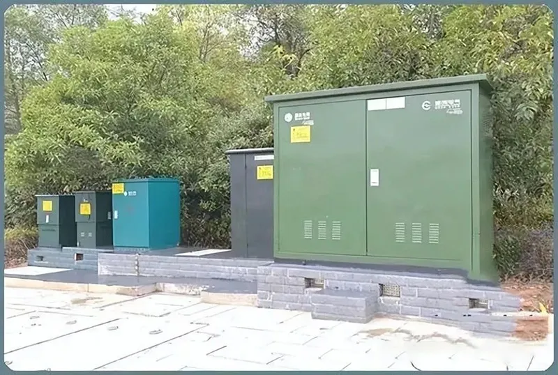
Designed for outdoor deployment, American-style RMUs are compact, sealed, and maintenance-free. They feature robust internal and external enclosures, often stainless steel, ensuring superior impact resistance and explosion protection. Pre-molded cable connectors simplify installation while maintaining reliable connectivity. These RMUs follow a common gas tank design, housing multiple feeders within a single body, offering high reliability and flexible switch arrangements.
(1) Common Gas-Tank Type
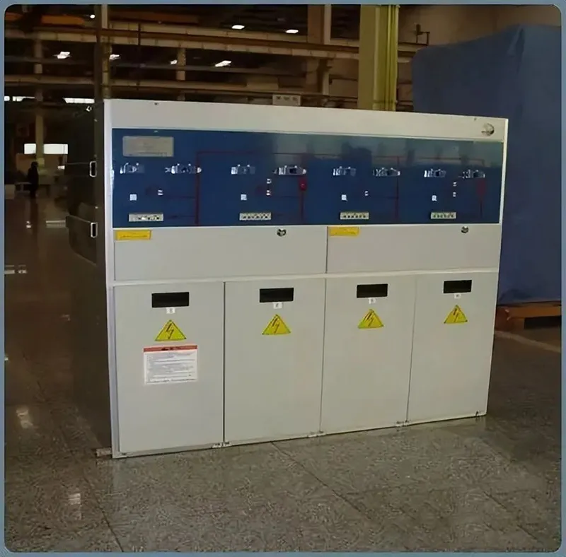
Built from independent compartments, each European-style RMU separates functional areas—main busbars, load switches, and combination units—into isolated modules. SF₆ gas-filled enclosures are welded with 3.0mm stainless steel using argon arc techniques. This modular design offers flexibility and scalability.
(2) Gas-Pocket Type
This version employs stainless-steel switch enclosures to divide the RMU into sub-chambers. SF₆ gas-insulated load switches are sealed within high-strength steel casings, crafted through cold-forging techniques, ensuring impeccable build quality and modular adaptability.
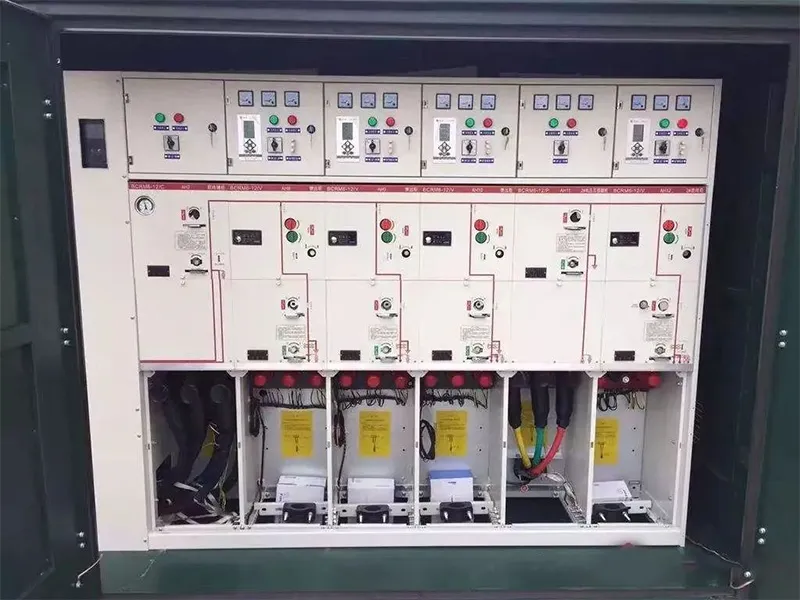
A typical RMU comprises four sections:
Switch Compartment: Houses the load and earthing switches sealed in metal enclosures. It includes arc-resistant contact systems, visible operating positions, and explosion vents.
Fuse Compartment: Integrates with the switch to form transformer protection circuits. High-voltage current-limiting fuses are encapsulated in epoxy for insulation and trigger switch tripping upon fault detection.
Operating Mechanism Compartment: Equipped with manually or electrically charged spring mechanisms for actuation. Indicators, mimic diagrams, interlocks, and status lights enhance operability and safety.
Cable Compartment: Positioned at the base, it accommodates incoming and outgoing cables, often fitted with surge arresters and grounding provisions.
A ring distribution network forms a closed-loop where power can flow from either direction. Each distribution branch can draw power from both its left and right feeders. In case of a fault on one side, supply continuity is maintained from the alternate path—achieving near dual-supply reliability from a single-source system.
Each branch is controlled by an RMU, which serves both as a feeder and a segment of the main ring busbar. These units use load break switches (typically SF₆ gas insulated) for routine current control and fuses for fault current isolation.
An RMU commonly includes:
Two cable feeder intervals
One transformer protection interval
SF₆ load break switches are favored for their robustness, long service life, and three-position operation (ON, OFF, and Earth). These units handle inductive and capacitive currents, operate reliably in harsh environments, and are optimal for urban and rural medium-voltage systems.
When paired with high-voltage fuses, SF₆ switches can seamlessly manage both operational and fault conditions. The fuse protects against short circuits, while the switch handles load currents. Triggered fuses automatically trip the switch across all phases.
Urban applications prefer outdoor RMUs built with fully sealed SF₆-insulated enclosures, meeting IP67 protection standards—capable of withstanding submersion and extreme weather. A typical setup uses a “two-in, one-out” configuration forming a “hand-in-hand” loop, ensuring high reliability and service continuity.
Ring main systems are prevalent in:
Industrial plants
Residential communities
Ports and high-rises
The busbars within RMUs must accommodate both local load currents and bypass currents supplying adjacent units. Popular product lines include HK-10, MKH-10, 8DH-10, XGN-15, and SM6.
Each RMU comprises multiple compartments:
Switch Chamber
Busbar Compartment
Cable Termination Section
Control and Protection Zone
Load Break Switch: Allows disconnection under load; not designed for frequent operations. Often integrated with fuses, these switches offer higher arc-extinguishing capabilities than isolators.
Isolator Switch: Ensures clear physical disconnection post breaker isolation, providing visible safety separation. Often used for auxiliary systems like PTs and arresters.
Circuit Breaker: Capable of managing fault currents and load interruptions, circuit breakers offer precise, timed protection under abnormal conditions.
Earthing Switch: Critical during maintenance to safely ground equipment, preventing accidental energization and dissipating residual charge.
Load Switch Cabinet
Load Switch-Fuse Combination Unit
Breaker Cabinets
Voltage and Current Measurement Units
Interlocking systems ensure safe operations, preventing misoperation such as earthing under load or switching without proper sequencing. Visual indicators and mechanical barriers further enhance reliability.
Switch or Isolator Compartment
Main Busbar Compartment
Breaker Terminal Compartment
Operating Mechanism Section
Protection and Control Compartment
These devices use SF₆ gas as both the insulating and arc-extinguishing medium, offering reliable three-position functionality and high dielectric strength.
More advanced than load switches, SF₆ breakers handle higher fault currents with minimal maintenance and superior switching endurance.
Mechanical interlocks prevent unsafe operations—ensuring, for example, that the earthing switch cannot be closed when the load switch is energized.
Modern RMUs incorporate:
Microprocessor-Based Protection Relays
Live-Line Indicators
Fault Locators
Temperature and Humidity Controllers
Incoming/Outgoing Cabinets: Control feeder entries and exits.
Protection Cabinets: Incorporate protective relays and fuses.
Measurement Cabinets: Host current and voltage transformers.
Special-Purpose Cabinets: Custom modules for specific user needs.
RMUs are core components in smart grid development, especially when paired with DTUs (Distribution Terminal Units).
Real-Time Monitoring: Observe loads remotely, enabling proactive planning and fault anticipation.
Remote Operation: Reduces manual intervention, with switching times dropping from 2.5 hours to 30 minutes.
Fault Automation (FA): Automatic fault isolation and service restoration, improving reliability from 99.96% to 99.997%.
A fully automated distribution loop can autonomously isolate faults, reroute power, and report status to a central system in under 2 minutes.
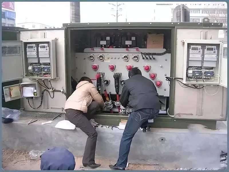
Proper transportation and unpacking practices ensure that the RMU arrives undamaged and ready for safe commissioning. RMUs should be stored in dry, ventilated environments away from corrosive agents.
The 10kV RMU stands as a cornerstone of modern medium-voltage power distribution, marrying reliability, modularity, and automation in a compact form. Whether deployed in urban substations or suburban developments, it ensures that power flows uninterrupted and safely—rain or shine, day or night.