
Load Break Switches for Pad-Mounted Transformers: Selection Guide
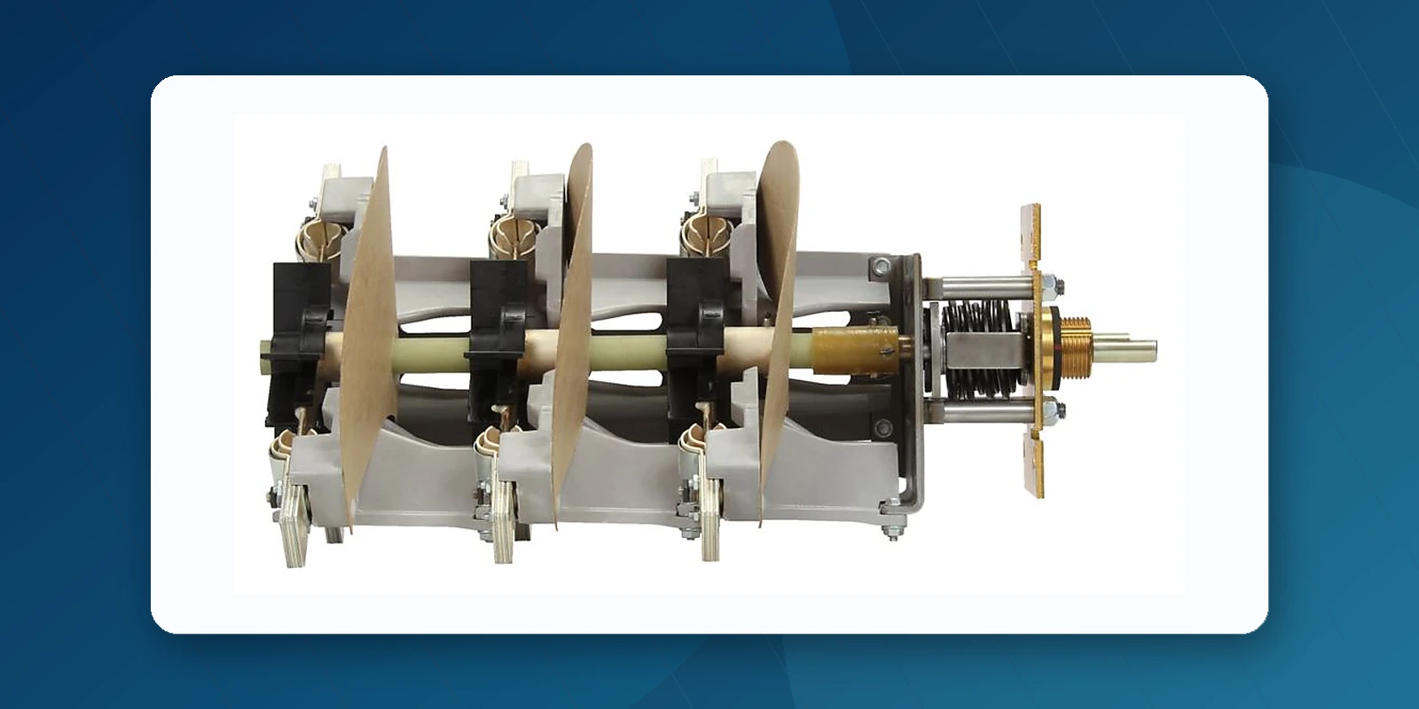
1. The Role of Load Break Switches in Transformer Design
Load break switches serve three essential functions in pad-mounted transformer applications:
- Circuit isolation — Disconnecting the transformer primary from the line for maintenance, testing, or emergency isolation. A visible break provides positive confirmation of de-energized state.
- Loop feed switching — In underground residential distribution (URD) systems, sectionalizing switches enable alternative source selection, rerouting power around faulted cable sections without interrupting service to healthy circuits.
- Source transfer — In commercial and industrial installations with dual primary feeds, the switch allows switching between normal and alternate power sources, often with make-before-break capability for uninterrupted transfer.
Eaton Cooper's under-oil design places the switch inside the transformer tank near the core/coil assembly. This configuration minimizes cable capacitance (a key factor in reducing ferroresonance risk) and protects the switching mechanism from environmental exposure.
2. Two-Position Load Break Switches (On/Off)
The two-position switch provides simple ON/OFF switching for single-source transformer connections. Its manually charged over-toggle stored spring mechanism ensures consistent, operator-independent operation — the spring drives the contacts open or closed in less than one cycle, regardless of how fast or slow the operator moves the handle.
Key Features:
- Stored spring mechanism — Independent of operator speed, ensures quick loadbreak/loadmake in under one cycle
- Double O-ring shaft sealing — Prevents oil leakage and moisture ingress over decades of service
- Three mounting options — Bolt-in place, weld-in bracket assembly, or easy-install ring mount system
- Tungsten-copper arcing contacts — Minimize arc erosion and extend contact life through thousands of operations
- Silver-plated copper blades — Keyed between vented rotor halves for precise alignment and low-resistance current path
- Internal mechanical stops — Restrict handle orientation to only two positions, preventing operator confusion
- Hotstick operable — Minimal input torque required for field operation
Two-Position Switch Ratings:
| Max Phase-to-Phase Voltage | Continuous Current | Switching Current | Magnetizing Interrupting | Cable Charging | 10-Cycle Fault Withstand (Sym) |
|---|---|---|---|---|---|
| 15.5 kV | 550 A | 550 A | 21 A | 10 A | 12 kA |
| 27.6 kV | 400 A | 400 A | 21 A | 25 A | 12 kA |
| 38 kV | 300 A | 300 A | 10.5 A | 20 A | 12 kA |
| 46 kV | 65 A | 65 A | 10.5 A | 15 A | 12 kA |
Popular two-position switch models include the LS2B338H3N2A (38kV, 300A) and LS2B612H3N1A (12/15kV, 630A).
3. Four-Position Sectionalizing Switches
Four-position sectionalizing switches serve URD loop feed and commercial/industrial dual-source applications. Unlike simple ON/OFF switches, they offer four distinct operating positions that enable flexible circuit reconfiguration without field cable work.
The switch rotates 360 degrees in either direction, allowing alternate source selection through sequential positions. Two blade configurations are available:
V-Blade Configuration
The V-blade arrangement connects the source to one of two load circuits, or isolates all circuits. This is the most common configuration for URD loop feed applications where a single transformer serves two radial cable runs. The V-blade switch provides clear visual indication of the connected circuit through its blade position.
T-Blade Configuration
The T-blade arrangement allows connection of the source to either or both load circuits, supporting more complex network configurations. This configuration is preferred for commercial/industrial installations where multiple service arrangements may be needed over the facility's lifetime.
Make-Before-Break Option
Both V-blade and T-blade switches are available with make-before-break design, which momentarily connects both sources during switching. This feature is critical for applications where even a momentary interruption is unacceptable — such as data centers, hospitals, or continuous-process industrial facilities. The momentary paralleling occurs within the switch's oil-immersed contacts, safely managing any circulating current.
Popular Four-Position Switch Models:
| Model | Voltage | Current | Configuration |
|---|---|---|---|
| LS4B615H3T16B | 15.5 kV | 630 A | T-blade, 3-phase |
| LS4RH3T16B | 24 kV | 400 A | T-blade, 3-phase |
| LS4RH3T12B | 15.5 kV | 630 A | T-blade, 3-phase |
| LS4BH3R16B | Varies | Varies | R-type (V-blade), 3-phase |
4. Ferroresonance Mitigation
Ferroresonance is a potentially destructive overvoltage condition that can occur in three-phase transformers with single-phase switching on cable-fed circuits. By installing the switch near the core/coil assembly and switching all three phases simultaneously, Eaton Cooper's sectionalizing switches significantly reduce ferroresonance risk. The under-oil design further suppresses the capacitive effects that contribute to this phenomenon.
For particularly sensitive applications, Eaton offers switch options with additional damping features. Our technical team at Jiuyingtech can help evaluate ferroresonance risk for your specific installation and recommend appropriate mitigation strategies.
5. Production Testing and Quality Assurance
Every Eaton Cooper load break switch undergoes production testing in accordance with Cooper Power Systems requirements, verifying:
- Contact resistance within specified limits
- Operating torque within acceptable range
- Proper blade alignment and contact pressure
- Dielectric integrity of insulation
- Mechanical endurance (operating cycle verification)
- Seal integrity of shaft O-ring system
Switches meet the full requirements of the latest revisions of both IEEE and IEC standards, ensuring global acceptance in transformer designs for any market.
Manufacturer Resources
Use the latest manufacturer literature for final ratings, ordering codes, installation, and safety requirements.
Frequently Asked Questions
When should I use a two-position load break switch?
Use a two-position design when the required function is straightforward ON/OFF connection or isolation and the transformer does not need loop-feed sectionalizing or multiple source positions.
What does a four-position sectionalizing switch do?
It provides multiple circuit states for loop-feed and source-routing applications. The exact T-blade or V-blade indexing must match the one-line diagram and operating philosophy.
Does the switch provide a visible open point?
An internal switch position alone should not be described as a visible break. Visible-break functionality depends on the equipment design and any dedicated viewing or external visible-break feature.
Need Load Break Switches for Your Transformer Design?
Jiuyingtech supports inquiries for 2-position and 4-position Eaton Cooper load break switches. Pricing, availability, documentation, and delivery estimate are confirmed for the exact catalog number.