
ELSP Current-Limiting Backup Fuses: Selection and Coordination
1. Why Current-Limiting Protection Matters
In an ideal world, a transformer's primary fuse would handle every fault condition — from a minor overload to a catastrophic internal winding failure. In reality, expulsion fuses like the Bay-O-Net have finite interrupting ratings. When fault currents exceed these limits (typically above 3,000-3,500A asymmetrical), the fuse may not clear the fault safely, potentially leading to equipment damage, fire, or tank rupture.
Current-limiting fuses solve this problem by using a fundamentally different operating principle. Instead of expelling arc products into the surrounding medium, the ELSP fuse contains the arc within a high-purity silica sand filler. The sand absorbs arc energy, melts into a glass-like fulgurite, and extinguishes the arc before the fault current reaches its natural peak. This "current limiting" action dramatically reduces both the peak current and the total energy (I²t) delivered to the fault.
2. ELSP Fuse Construction: Engineered for Energy Absorption
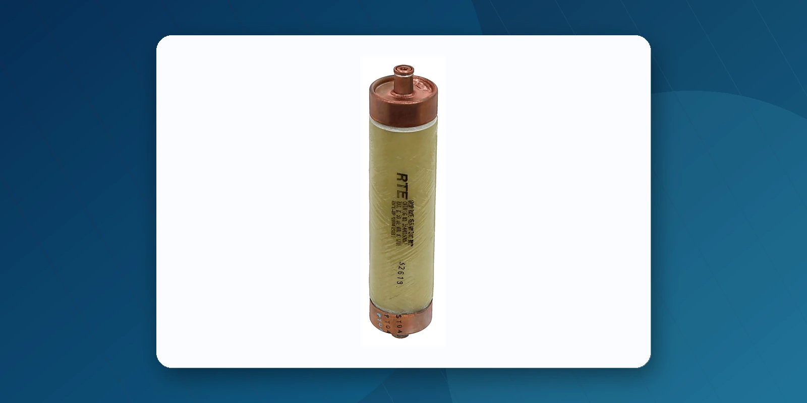
The ELSP fuse incorporates several design features that enable its high-performance current-limiting action:
- High-purity silica sand filler — Precisely graded particle size, purity, and compaction provide the heat-absorbing and arc-quenching properties necessary for consistent clearing and low energy let-through levels
- Fiberglass housing — Provides mechanical strength to withstand the high internal pressures generated during fault interruption, while maintaining electrical insulation integrity
- Mica spider element support — Maintains stable winding of the fuse element without generating gas or pressure buildup during normal operation, ensuring long-term reliability
- Solid copper end caps with brass inserts — Tapped for standard 1/4-inch - 20 x 1/2-inch lead hardware, providing robust, low-resistance electrical connections
- Silver fuse element — Precision-engineered notched ribbon design ensures predictable melting characteristics and consistent current-limiting performance across the full fault current range
3. Complete Product Range: CBUC Series
| Voltage Class | Model Series | Available Current Ratings | Typical Transformer Primary Voltage |
|---|---|---|---|
| 8.3 kV | CBUC080XXC/D100 | 30A, 50A, 80A, 125A, 150A, 165A, 180A | 4.16 kV - 8.3 kV |
| 15.5 kV | CBUC150XXC/D100 | 30A, 40A, 50A, 65A, 80A, 100A, 125A, 150A, 165A, 180A | 12.47 kV - 15.5 kV |
| 23 kV | CBUC230XXC/D100 | 30A, 40A, 50A, 65A, 80A, 100A, 125A, 150A, 165A | 22.9 kV - 23 kV |
| 38 kV | CBUC380XXD100 | 65A, 80A, 100A, 120A, 140A | 34.5 kV - 38 kV |
Note: "C" suffix indicates lower current range (typically 30A-100A), "D" suffix indicates higher current range (typically 100A-180A). The complete model number follows the format CBUC[Voltage][Current][C/D]100 — for example, CBUC15150D100 is a 15.5kV, 150A ELSP fuse.
4. The Two-Part Protection System in Practice
The ELSP fuse is never used alone — it always operates as part of a coordinated two-part protection scheme:
Part 1: Primary Protection (Bay-O-Net or MagneX)
The Bay-O-Net fuse or MagneX interrupter handles all routine fault events: secondary faults, overloads, moderate primary faults, and through-faults. These devices are resettable (MagneX) or easily replaceable (Bay-O-Net) from outside the transformer.
Part 2: Backup Protection (ELSP)
The ELSP current-limiting fuse only operates when fault current exceeds the primary device's interrupting capability — typically during severe internal transformer faults. Since such events are rare, the ELSP fuse should ideally never need replacement over the transformer's service life.
Coordination Requirements
Proper coordination means the ELSP fuse's minimum interrupting rating must be above the Bay-O-Net or MagneX interrupter's maximum interrupting capability. This ensures no "gap" in protection coverage. Eaton provides coordination tables and time-current curves to verify proper selection for each specific combination of primary device and ELSP fuse.
5. Parallel Operation for Higher Current Ratings
For transformers exceeding the maximum single-fuse current rating, two ELSP fuses can be connected in parallel. This configuration effectively doubles the continuous current capacity while maintaining full current-limiting protection. Parallel operation is commonly used for larger substation-type transformers and high-capacity distribution units above 2,500 kVA.
When ordering fuses for parallel operation, both fuses must be of identical rating and from the same production batch to ensure balanced current sharing during normal operation and simultaneous operation during fault conditions.
6. Installation and Maintenance Considerations
ELSP fuses are designed for under-oil installation in transformer tanks filled with mineral oil, Envirotemp FR3 fluid, or approved equivalents. Key installation requirements include:
- Proper mounting orientation to ensure adequate oil circulation around the fuse body
- Sufficient clearance from grounded surfaces to prevent flashover during operation
- Secure mechanical mounting to withstand magnetic forces during high-fault operation
- Clean, tight electrical connections using the standard 1/4-20 threaded brass inserts
Because ELSP fuses are not field-replaceable (unlike Bay-O-Net links), their replacement requires opening the transformer tank. This reinforces the importance of correct initial selection and coordination — the ELSP fuse should be sized to never operate on through-faults or secondary faults that the Bay-O-Net can handle.
7. Quality and Testing
Every ELSP fuse design undergoes rigorous testing to verify:
- Interrupting capability at maximum rated voltage and current
- Current-limiting performance (peak let-through current, I²t)
- Temperature rise at rated continuous current
- Coordination with upstream and downstream protective devices
- Long-term thermal aging resistance
Certified test reports are available for all standard ratings, and Jiuyingtech can provide these upon request with your order.
Manufacturer Resources
Use the latest manufacturer literature for final ratings, ordering codes, installation, and safety requirements.
Frequently Asked Questions
Why is an ELSP fuse used with a Bay-O-Net fuse?
The Bay-O-Net device handles the lower-current portion of the protection range, while the ELSP backup fuse limits and interrupts high fault currents. The pair must be selected from approved coordination information.
Can ELSP fuses be connected in parallel?
Certain applications use matched ELSP fuses in parallel to obtain higher current capability. The arrangement must follow the manufacturer’s catalog and transformer design requirements.
Is an ELSP fuse suitable for mineral oil and FR3 fluid?
Eaton documents ELSP use in transformer oil, Envirotemp FR3 fluid, or an approved equivalent. Always verify the exact catalog number and current manufacturer instructions.
Need ELSP Current-Limiting Fuses?
Jiuyingtech supports inquiries for CBUC series ELSP fuses across the applicable voltage classes. Availability, production origin, delivery estimate, and available test documentation are confirmed for each catalog number and quotation.